Mitsubishi P15 Service Manual Page 11
- Page / 28
- Table of contents
- BOOKMARKS
- R407C R22R410A 1
- TECHNICAL CHANGES 2
- SAFETY PRECAUTION 2
- Gravimeter 3
- PART NAMES AND FUNCTIONS 6
- Display Section 7
- Operation Section 7
- ON/OFF TEMP 8
- SPECIFICATION 9
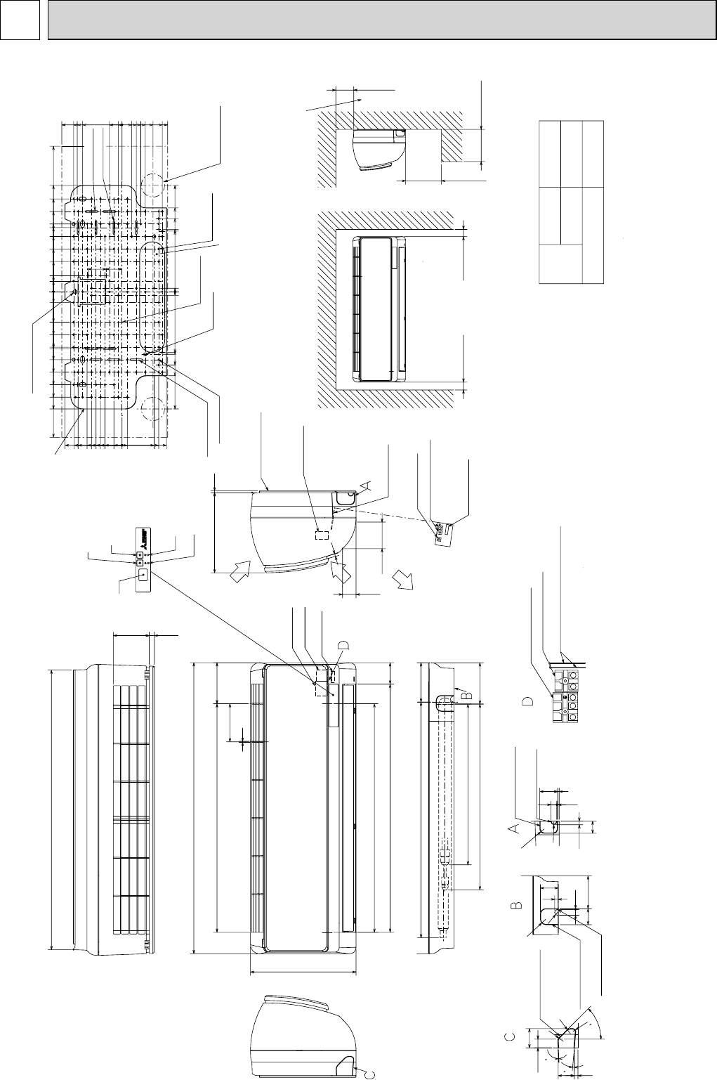
- OUTLINES AND DIMENSIONS 11
- PKFY-P20, 25VBM-E 12
- PKFY-P15VBM-E 13
- PKFY-P20, 25VBM-ER1 13
- PKFY-P15, 20, 25VBM-ER2 13
- TROUBLESHOOTING 14
- REFRIGERANT SYSTEM DIAGRAM 14
- Linear expansion valve 15
- Valve position (capacity) 16
- Fan operation at Heating mode 17
- Models SW2 17
- Effective 18
- 8-3. TEST POINT DIAGRAM 19
- 1234 56789 21
- DISASSEMBLY PROCEDURE 22
- Front panel 25
- Set screws 25
- Photo 10 28
- Photo 11 28
Related products and manuals for Split-system air conditioners Mitsubishi P15


 (104 pages)
 (47 pages)
© 2020, manymanuals.com. All rights reserved. | 0.042 s |
 Manymanuals.com
 Manymanuals.de
 Manymanuals.fr
 Manymanuals.it
 Manymanuals.pl
 Manymanuals.cz
 Manymanuals.es
 Manymanuals-pt.com
Comments to this Manuals